- Vetrivel Madhesan
- October 30, 2025
Getting Started with Unified Power Format (UPF) | Part 1
1 Introduction to UPF and Power-Aware Simulation
Modern SoC designs demand aggressive low-power techniques to meet performance and energy efficiency goals.
However, managing power at the architectural level is not straightforward. Techniques like power gating, voltage scaling, and isolation logic can be tedious and error-prone when handled manually. Inserting power switches, level shifters, and retention cells without disrupting RTL functionality adds significant complexity — especially in large, hierarchical designs.
A key component in low-power design is the Unified Power Format (UPF), defined by the IEEE 1801 standard, which specifies how to describe power intent in digital systems.
While UPF is the most prevalent standard, other formats like CPF (Common Power Format), manual constraints, and tool-specific power directives are also used in the industry. Each has its own pros and cons.
In this blog, we’ll focus on UPF — exploring what it offers, how it helps automate power intent, and how it supports accurate and scalable power-aware simulation to catch critical issues early in the design cycle.
2 What Is UPF?
UPF is a TCL-based specification used to define a design’s power intent separately from its RTL logic, enabling independent control of power architecture. It tells the tools:
- What power domains exist in the design?
- Which power rails connect to which blocks?
- When the blocks should power up or power down
- What the voltage levels are for each domain
- How the logic is handled when power is removed (e.g., isolation, retention, level shifters)
By separating power intent from functional logic, UPF enables designers to implement and verify low-power strategies without modifying RTL code. This leads to more efficient power usage, reduced leakage, and better control over dynamic power.
3 What Is Power-Aware Simulation?
Consider UPF-based power-aware simulation as an enhanced and more accurate approach compared to traditional RTL simulation.
3.1 In RTL Simulation
- Only logic states (0 or 1) are considered.
- Power supplies (like VDD or VSS) are assumed to be ideal and always present.
- Signals behave deterministically, without modeling power failure scenarios.
3.2 In Power-Aware Simulation
- The simulation includes power intent defined in the UPF file.
- Signals can take on values 0, 1, X (unknown), and Z (high impedance), depending on power conditions.
- It models what happens when:
- Power rails are disconnected.
- Voltage levels mismatch
- Blocks are powered down mid-operation.
This enables the detection of issues such as:
- Glitches or invalid logic when domains are off.
- Retention/isolation failure
- Power sequencing violations
3.3 Example: Logic Without and With UPF
3.3.1 RTL Simulation
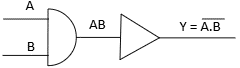
In this setup, the output Y depends solely on inputs A and B. Power conditions are not modelled at all.
3.3.2 Power-Aware Simulation with UPF
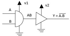
Now, Y is influenced not only by A and B, but also by the availability of power supplies V1, V2, and VSS. If any supply is missing or turned off, the output may become X or Z, revealing potential power bugs early in the flow.
3.4 Why It Matters
Power-aware simulation is typically done before synthesis, and helps designers:
- Catch functional errors due to power management strategies.
- Validate UPF constraints like isolation and retention.
- Ensure robust behavior in multi-voltage and multi-domain systems.
By simulating real-world power scenarios, UPF lets engineers design hardware that’s not only functional — but power safe.
4 Understanding UPF Types: Flat vs Hierarchical
When implementing power intent in digital designs using the Unified Power Format (UPF), designers can choose between two modelling approaches: Flat UPF and Hierarchical UPF. Each has its advantages depending on the size and complexity of the design.
4.1 Flat UPF
Flat UPF specifies the entire power intent at a single level, usually at the top of the design. In this method
- Power domains, supply sets, and power states are defined globally, without considering module boundaries.
- It’s a straightforward, less abstract model ideal for:
- Small designs
- Prototyping
- Projects with a shallow or no hierarchy
Use Case: A single-core processor or simple peripheral controller with minimal power domains.
4.2 Hierarchical UPF
Hierarchical UPF models power intent in alignment with the RTL hierarchy, assigning power domains and constraints at various levels of the design. It supports:
- Modular power definition at block, subsystem, and top-level hierarchies
- Better reuse of power intent for IPs or reusable blocks
- Easier integration and scalability for complex SoCs
Use Case: Large-scale SoCs, multi-core architectures, or designs integrating multiple IPs with different power domains.
4.3 Flat vs Hierarchical: Which One to Choose?
Feature | Flat UPF | Hierarchical UPF |
Complexity | Simple | Scalable and modular |
Suitable for | Small designs | Large, hierarchical designs |
Reusability | Low | High |
Maintainability | Harder as design grows | Easier in complex systems |
Alignment with RTL | Top-level only | Follows design hierarchy |
5 UPF Versions
UPF Version | Release Year | Key Enhancements |
UPF 1.0 (Accellera) | 2007 | Introduced basic power intent modelling with flat UPF and fundamental power controls. |
UPF 1.1 (Accellera) | 2009 | Provided clarifications and minor enhancements for early adopters. |
UPF 2.0 (IEEE 1801-2009) | 2010 | Added support for hierarchical UPF, supply sets, and improved modular design intent. |
UPF 2.1 (IEEE 1801-2013) | 2013 | Introduced power state tables (PSTs), power modes, and enhanced simulation semantics. |
UPF 3.0 (IEEE 1801-2015) | 2016 | Enabled library-level power intent, introduced IMDB, and improved usability. |
UPF 3.1 (IEEE 1801-2018) | 2020 | Enhanced IP portability, added support for dynamic voltage scaling and better verification features. |
6 UPF Constraints
S.No | Keyword | Description |
1 | create_power_domain | Defines a power domain at the top-level or within a module. This groups logic that shares a common power intent. |
2 | create_power_switch | Describes how power is gated for a domain, typically through enable signals when the logic is inactive. |
3 | set_isolation | Specifies how signals to/from a powered-down domain should behave, typically inserting isolation cells to avoid corruption. |
4 | set_isolation_control | Defines the control logic that activates isolation cells based on domain power status or isolation signals. |
5 | set_level_shifter | Specifies where and how level shifters should be inserted when signals cross between domains operating at different voltage levels. |
6 | set_retention | Indicates which registers or flops retain their values during power-down, using retention strategies. |
7 | set_retention_control | Defines the control logic for retention behaviour (e.g., when to save or restore values). |
8 | add_power_state | Defines named power states for a domain, including voltage levels, control logic, and simulation behaviour (like NORMAL or CORRUPT). |
9 | create_pst | Creates a Power State Table (PST) that lists legal combinations of power states across multiple domains or supply sets. |
10 | add_pst_state | Adds specific power state combinations to a PST, tying together individual domain states for simulation and analysis. |
11 | associate_supply_set | Links a supply set to domain behaviour such as isolation, retention, or level shifters — defining the default power behaviour. |
12 | create_supply_port | Represents a physical supply pin, such as VDD or VSS, which can be connected externally or to a supply net. |
13 | create_supply_net | Defines a logical representation of a power or ground net, which can be connected to ports and domains. |
14 | connect_supply_net | Connects a supply net to one or more supply ports, enabling physical connectivity. |
15 | create_supply_set | Groups one or more supply nets (e.g., power and ground) into a named supply set for assignment to a domain or block. |
7 The Challenges of Manual Power Management
Designing for low power isn’t just about turning off blocks when they’re idle — it involves careful coordination between power domains, signal integrity, and timing.Some frequently encountered challenges include:
- Implementing power gating: introducing power switches without modifying the RTL can be tricky and, if not done carefully, may result in functional issues or synthesis inconsistencies.
- Managing level shifters: Signals crossing between domains with different voltage levels need properly placed level shifters. Doing this manually is error-prone and hard to scale in large designs.
- Inserting isolation logic: When a power domain is turned off, isolation cells must be used to prevent undefined values from affecting active logic — again requiring careful RTL and constraint coordination.
- Maintaining RTL integrity: Embedding power intent directly in RTL quickly leads to tangled code, making reuse, verification, and updates much harder.
All these tasks, if done manually, increase the risk of functional bugs, late-stage rework, and verification complexity.
8 Case Study: Power-Aware Design of a Dual-Core System with Shared Memory
Let’s consider a simplified SoC architecture with the following blocks:
- Core A and Core B –two processor cores.
- Shared SRAM — common memory block accessible by both cores
- Interconnect Bus — connects cores and memory.
- Power to each core can be independently turned off to reduce energy consumption.
8.1 Power Management Requirements
- Core A and Core B should be in separate power domains so they can be turned off independently.
- The shared SRAM should remain powered to retain data, even if one or both cores are off.
- Level shifters are needed between cores and memory if voltage levels differ.
- Isolation logic is required at the output of each core when it’s powered down.
- Retention registers may be used in the cores to preserve key registers during power down.
8.2 How UPF Helps
With UPF, you can define this power intent separately from the RTL.
Example of Flat UPF
#—————————————————-
# Power Domains
#—————————————————-
create_power_domain CORE_A_DOMAIN -elements { core_a }
create_power_domain CORE_B_DOMAIN -elements { core_b }
create_power_domain MEM_DOMAIN -elements { shared_sram }
#—————————————————-
# Supply Nets & Supply Sets
#—————————————————-
create_supply_net VDD_A
create_supply_net VDD_B
create_supply_net VDD_MEM
create_supply_net VSS
create_supply_set CORE_A_SUPPLY -power_nets { VDD_A } -ground_nets { VSS }
create_supply_set CORE_B_SUPPLY -power_nets { VDD_B } -ground_nets { VSS }
create_supply_set MEM_SUPPLY -power_nets { VDD_MEM } -ground_nets { VSS }
associate_supply_set -domain CORE_A_DOMAIN -supply_set CORE_A_SUPPLY
associate_supply_set -domain CORE_B_DOMAIN -supply_set CORE_B_SUPPLY
associate_supply_set -domain MEM_DOMAIN -supply_set MEM_SUPPLY
#—————————————————-
# Isolation Logic for Core A
#—————————————————-
set_isolation ISOLATE_A -domain CORE_A_DOMAIN \
-isolation_output high -clamp_value 0
set_isolation_control ISOLATE_A \
-isolate_signal iso_a -isolate_expr { !power_good_a }
#—————————————————-
# Isolation Logic for Core B
#—————————————————-
set_isolation ISOLATE_B -domain CORE_B_DOMAIN \
-isolation_output high -clamp_value 0
set_isolation_control ISOLATE_B \
-isolate_signal iso_b -isolate_expr { !power_good_b }
#—————————————————-
# Level Shifters
# (assuming voltage difference between cores and memory)
#—————————————————-
set_level_shifter LS_A_TO_MEM -from CORE_A_DOMAIN -to MEM_DOMAIN
set_level_shifter LS_B_TO_MEM -from CORE_B_DOMAIN -to MEM_DOMAIN
#—————————————————-
# Retention (optional for both cores)
#—————————————————-
set_retention RET_A -domain CORE_A_DOMAIN -retention_cells { ret_reg_a }
set_retention_control RET_A -save_signal save_a -restore_signal restore_a
set_retention RET_B -domain CORE_B_DOMAIN -retention_cells { ret_reg_b }
set_retention_control RET_B -save_signal save_b -restore_signal restore_b
Example of Hierarchical UPF
A Hierarchical UPF structure example is illustrated below.
- top.upf (Reads sub-UPFs, defines supply nets/sets, Associates supplies, Defines top-level level shifters, isolation, etc.)
- core_a.upf (Local domain, retention, isolation)
- core_b.upf (Local domain, retention, isolation)
- shared_sram.upf (Always-on domain)
core_a.upf
# Set the scope to core_a instance in RTL hierarchy
set_scope core_a
# Define power domain for Core A
create_power_domain CORE_A_DOMAIN -elements { core_a }
# Retain register values during power down
set_retention RET_A -domain CORE_A_DOMAIN -retention_cells { ret_reg_a }
# Define control signals for save/restore behavior
set_retention_control RET_A -save_signal save_a -restore_signal restore_a
# Apply isolation when Core A is powered down
set_isolation ISOLATE_A -domain CORE_A_DOMAIN -isolation_output high -clamp_value 0
# Define when isolation logic is active
set_isolation_control ISOLATE_A -isolate_signal iso_a -isolate_expr { !power_good_a }
core_b.upf
# Set the scope to core_b instance
set_scope core_b
# Define power domain for Core B
create_power_domain CORE_B_DOMAIN -elements { core_b }
# Add retention strategy for Core B
set_retention RET_B -domain CORE_B_DOMAIN -retention_cells { ret_reg_b }
# Control signals for Core B retention
set_retention_control RET_B -save_signal save_b -restore_signal restore_b
# Add isolation for Core B outputs
set_isolation ISOLATE_B -domain CORE_B_DOMAIN -isolation_output high -clamp_value 0
set_isolation_control ISOLATE_B -isolate_signal iso_b -isolate_expr { !power_good_b }
shared_sram.upf
# Set scope to the shared memory instance in the RTL
set_scope shared_sram
# Define a power domain for the shared memory
# Memory must remain powered at all times to retain data
create_power_domain MEM_DOMAIN -elements { shared_sram }
top.UPF
# Read in sub-UPF files for core_a and core_b
read_upf core_a.upf
read_upf core_b.upf
# Set top-level scope
set_scope top
# Define power domain for shared memory
create_power_domain MEM_DOMAIN -elements { shared_sram }
# Create global supply nets
create_supply_net VDD_A
create_supply_net VDD_B
create_supply_net VDD_MEM
create_supply_net VSS
# Group supply nets into supply sets for each domain
create_supply_set CORE_A_SUPPLY -power_nets { VDD_A } -ground_nets { VSS }
create_supply_set CORE_B_SUPPLY -power_nets { VDD_B } -ground_nets { VSS }
create_supply_set MEM_SUPPLY -power_nets { VDD_MEM } -ground_nets { VSS }
# Associate supply sets with respective power domains
set_domain_supply_net CORE_A_DOMAIN -primary CORE_A_SUPPLY
set_domain_supply_net CORE_B_DOMAIN -primary CORE_B_SUPPLY
set_domain_supply_net MEM_DOMAIN -primary MEM_SUPPLY
# Define level shifter between Core A and shared memory (if voltage differs)
set_level_shifter LEVELSHIFT_A_TO_MEM -from CORE_A_DOMAIN -to MEM_DOMAIN
# Define level shifter between Core B and shared memory
set_level_shifter LEVELSHIFT_B_TO_MEM -from CORE_B_DOMAIN -to MEM_DOMAIN
8.3 Power-Aware Simulation Setup
In a UPF power-aware simulator, these constraints guide how the system behaves during simulation. For example:
- When Core B is powered down, the simulator inserts ‘X’ or ‘Z’ on its outputs, and the isolation logic kicks in to prevent glitches on the bus.
- When Core A operates at a lower voltage than the shared memory, level shifters are required to translate signals safely and correctly between the two voltage domains.
- If Core A is power-gated and then re-enabled, retention logic ensures its state is restored correctly. Just as it would be in silicon.
9 Best Practices for Low-Power Design Using UPF
Implementing UPF effectively isn’t just about using the right syntax, it’s about planning and integrating power intent early and cleanly into your design methodology. Here are some proven best practices:
9.1 Define Power Domains Early in the Design Flow
- Start partitioning your system into power domains during architecture or RTL planning.
- Early domain definition helps drive RTL structure, floor planning, and verification strategies.
- Document assumptions like which blocks can be power-gated and which need always-on behavior.
9.2 Use a Hierarchical and Modular UPF Structure
- Structure your UPF to align with the RTL hierarchy, using modular blocks that support reuse across different parts of the design.
- For IP-based or multi-team environments, Hierarchical UPF makes integration and debugging easier.
- Keep local power intent with the IP and integrate global power strategy at the top level.
9.3 Keep RTL Power-Agnostic
- Don’t hard-code power gating, isolation logic, or retention flops in RTL.
- Let UPF specify where and how these are applied. This keeps RTL reusable and clean.
9.4 Run Power-Aware Simulations Early
- Perform UPF-aware simulation as soon as functional RTL is available.
- Identify potential issues such as missing isolation, signal corruption, or power sequencing errors early in the design flow, before reaching synthesis.
- Use simulation coverage to evaluate power state transitions and corner cases.
9.5 Collaborate Across Teams
- Power intent affects RTL, verification, physical design, and software teams.
- Regular reviews and sharing of UPF assumptions help avoid late-stage surprises.
9.6 Leverage Tool Automation
- Use synthesis and P&R tools that support UPF 2.1+ or 3.0+ for better automation of retention, isolation, and power switch handling.
- Trust the tools to insert logic. but always validate it through simulation and analysis.
10 Conclusion
UPF has evolved into a powerful abstract layer for managing power intent in complex SoCs. By decoupling functional logic from power architecture, it enables:
- Modular design and reuse
- Early detection of power-related issues
- Efficient power-aware verification
Whether you’re using flat UPF for quick prototyping or hierarchical UPF for scalable SoC design, understanding and applying the right constraints is critical for successful low-power implementation.