- Athira R Variar
- June 4, 2025
Simplifying Formal Verification Debugging with Auto-generated Testbenches – Explained Using the Conformal LEC Tool
Introduction
Formal verification is a highly effective method for ensuring the correctness of designs. Logical Equivalence Checking (LEC) is one such formal verification technique that verifies the equivalence of the logic in an updated RTL/design. Cadence’s Conformal LEC is a powerful tool designed to perform this check, comparing two RTLs and ensuring their logical equivalence across all input combinations, including corner cases.
However, if the tool detects a non-equivalence between the two logics, pinpointing the exact mismatch can be a challenging task, especially as the complexity of the design increases. The method described below provides an effective way to ease the debugging process. This approach combines both functional and formal verification but eliminates the need for manually writing the testbench. Automation via Python makes this process more efficient.
Example Case and the challenges in the Traditional Method.
The example given below is an equivalence check of simple combinational logic executed in 2 different forms and this paper illustrates the ease of debug in the novel technique compared to the traditional technique. Cadence Conformal LEC is the tool used here.
Using Conformal LEC, we can identify the specific input combinations where the logical equivalence check fails, for each output signal in the design. The tool also helps in diagnosing the gates that cause logical mismatches.
Our reference model is referred to as golden, and the DUT is referred to as revised.
Given below is an example case:
The codes given below is for a simple combinational logic. In this res_1 and res_2 are 2 representations of X0R and XNOR gates respectively and res_3 and res_4 are De Morgan’s law representation.
Golden RTL is
module RTL_golden( a, b, c, d, res); input wire a; input wire b; input wire c; input wire d; output reg res; reg res_1; reg res_2; reg res_3; reg res_4; always@(*) begin //res_1 is an XOR gate res_1 = (a^b); //res_2 is an XNOR gate res_2 = (c~^d); //res_3 and res_4 represents De Morgan’s law res_3 = !(a|b); res_4 = !(a*b); res = (res_1 | res_2) & (res_3 | res_4); end endmodule |
Revised RTL is a different representation of same logic
module RTL_revised( a, b, c, d, res); input wire a; input wire b; input wire c; input wire d; output reg res; reg res_1; reg res_2; reg res_3; reg res_4; always@(*) begin //res_1 is an XOR gate //res_2 is an XNOR gate res_2 = ((c*d)|(!c*!d)); //res_3 and res_4 represents De Morgan’s law res_3 = (~a)*(~b); res_4 = (~a) | ~(b); res = (res_1 | res_2) & (res_3 | res_4); end endmodule |
For running the tool, the user needs to create a do file which will have the instructions given to the tool. A basic do file template is as below, the file name should have an extension .do.
//The below code will set the screen display off, we can give the log file path and can turn off the abort
set screen display off set log file //folder name/lec.log set dofile abort off
//both golden and revised designs are read in the below steps.
read design
<path to the file>/RTL_golden.v
-Verilog -Golden -sensitive
-continuousassignment Bidirectional -nokeep_unreach -nosupply
read design
/ <path to the file> /RTL_revised.v
-Verilog -Revised -sensitive
-continuousassignment Bidirectional -nokeep_unreach -nosupply \
set system mode lec
//below step will add and compare all the output points
add compared points -all
compare
//the non-equivalent points are diagnosed and written in the tcl file in the below steps. All the input points which are causing non equivalence are identified and the input value is analyzed.
diagnose -noneq -verbose -summary -revised
report test vector -noneq -ncsim > test_vector.tcl \
Reset
Both logics are equivalent here. So, the tool will give the output res as equivalent.
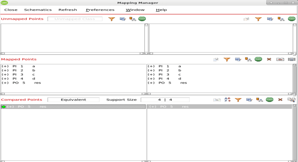
Consider the case where designer missed to add the not operand for the res_2 calculation and res_2 logic is now written as
res_2 = ((c*d) | (c*!d));
This will change the final result res.
The tool will report non-equivalence for the output res in this case.By opening the lec GUI we will be able to see the results.
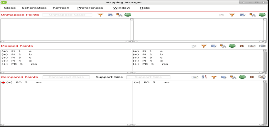
From the diagnose option in the tool, we can list out all the combination of inputs where the output mismatches. diagnose -noneq -verbose -summary –revised command in the do file will help to analyze all the non-equivalent points and find this using the script without running the GUI.
This is one of the advantages of formal verification. In traditional functional verification, it may need several runs to find the corner cases.
But the challenge comes in the debugging part. The traditional method is to use the schematics from the tool.
Below are the schematics for this case for golden and revised models.
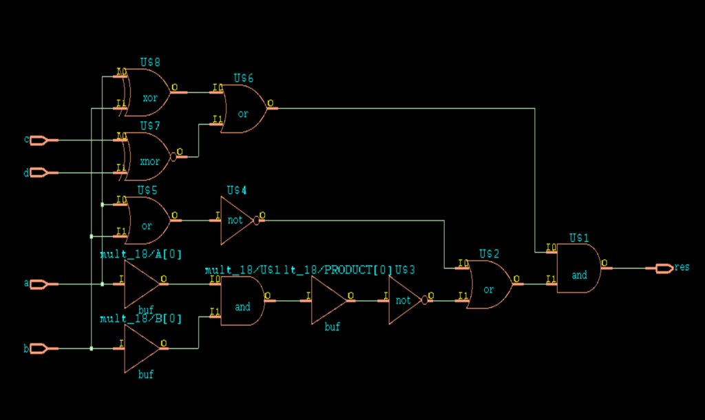
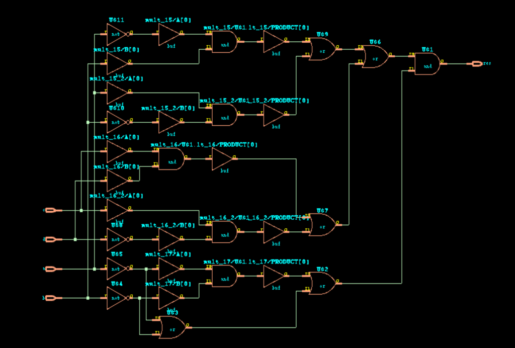
But from this, it is difficult to debug the exact point of mismatch and which sub logic (res1, res_2 ,res_3 or res_4) is causing the issue.
Given example is simple logic. But still the schematics are very difficult to decode.
For real scenarios where we have complex logics, it is a tedious task to debug using schematics.
The new method explained below will be helpful in this case.
Simplified Method of Debugging fails or Non-equivalence
The diagnostic details from the tool can easily be extracted into a TCL file using the diagnose -noneq property of the tool. With Python automation, the TCL files can be read, and Verilog testbenches can be generated for the non-equivalent output signals. These testbenches will drive the inputs corresponding to the mismatched output signals.
Given below is the detailed explanation:
The diagnostic information of non-equivalent points can be easily written into the tcl file adding the below command.
report test vector -noneq -ncsim > test_vector.tcl
Given below is the sample of tcl file generated using the tool. It will force the inputs with one of the failing combinations.We can see in both golden and revised code, each of the inputes are forced to the value which is causing non-equivalence.
// Confirm all Non-equivalent compared points
proc golforce1 {index} {
#this is for setting vector of res
if {$index == 0} {
force RTL_golden.a 0
force RTL_golden.b 0
force RTL_golden.c 1
force RTL_golden.d 0
}
}
proc revforce1 {index} {
#this is for setting vector of res
if {$index == 0} {
force RTL_revised.a 0
force RTL_revised.b 0
force RTL_revised.c 1
force RTL_revised.d 0
}
}
This data will be useful in creating a Verilog testbench, and this can be automated easily using a Python script. Given below is the sample testbench script which can be used for the above example. In the script, we will go through the tcl file generated from the tool which will give the input combinations which is causing non equivalence for an output. Function read_test_vector () will read the tcl file and there we can save the input signals and corresponding values to python dictionaries. As coded below, self.inputD will have the information about input signals and corresponding values.
Create_test_bench() is the function which develop the tesbench files.The function will read the input dictionaries corresponding to golden and revised and write in to the verilog file.
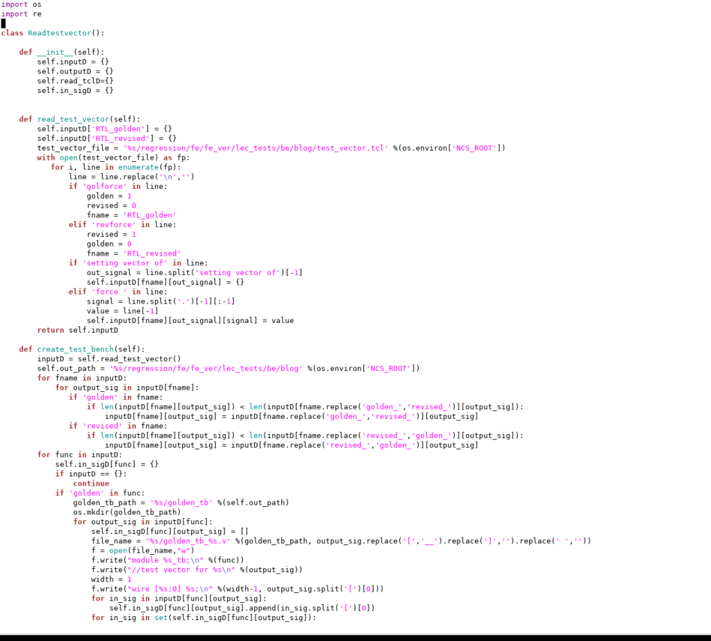
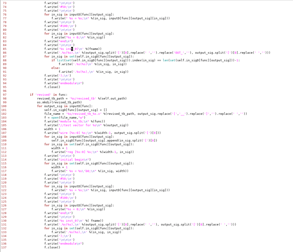
This will generate a verilog testbench which is given below
module RTL_golden_tb; //test vector for res wire [0:0] res; reg [0:0] d ; reg [0:0] b ; reg [0:0] a ; reg [0:0] c ;
initial begin d = 1’b0; b = 1’b0; a = 1’b0; c = 1’b0;
#50;
a = 0; b = 0; c = 1; d = 0;
#100;
a = 0; b = 0; c = 0; d = 0; end
RTL_golden inst_0( .res(res), .d (d ), .b (b ), .a (a ), .c (c ) );
endmodule
Similarly a testbench will be created for revised model also.
We can easily simulate it and debug using any waveform viewer.

From these waveforms we can easily figure out that the issue is in the res_2 calculation. This will narrow down the issue and make the debugging easy.
Conclusion
Formal verification is used to check the correctness of a design through mathematical methods. It can evaluate all possible behaviors of a system and is particularly effective in identifying corner cases. However, the challenge lies in the debugging process. The method described in this paper leverages the advantages of both formal and functional verification, while eliminating the need for writing manual test benches.


