Introduction
In the automotive industry, safety plays an immensely crucial role. All critical systems of the automobile need to pass stringent functional safety requirements. Any existing or new feature addition needs to pass various tests to confirm that it complies with high-grade user safety. Hence, there is a need for strategic analysis of functional features before launching new automobiles to the public.
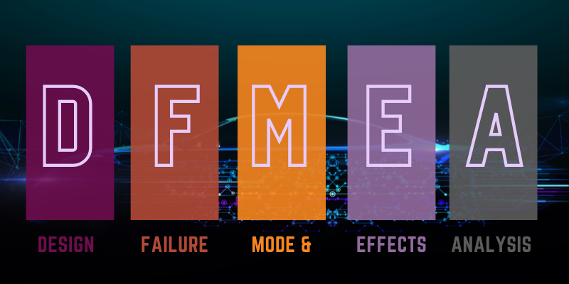
DFMEA
Design Failure Mode & Effects Analysis (DFMEA) is a systematic analysis process where the potential failures are identified and evaluated. DFMEA projects the outcomes and effects of these failures by analyzing the overall design architecture of product systems and components. It specifies how to eliminate or minimize the possible effects of design failure. Basically, DFMEA lets us know about what might go wrong, how bad the effect may be and how to prevent or mitigate the failure. DFMEA helps engineers detect failures at the earliest possible moment so they can be corrected early, without significant cost.
The main strategic flow followed is:
- Failure mode: Listing all potential failures by analyzing in all possible ways.
- Failure effects: The resulting consequences of each potential failure are noted.
- Failure causes: Various reasons which might result in the above listed potential failures are derived.
- Failure severity: A number from pre-defined range is assigned based on failure severity rate.
Here we follow only Failure mode and Failure causes in DFMEA flow.
Requirements and Specifications
Each IP has a set of Component Requirements (CR), Component Safety Requirements (CSR) and Design specifications.
- Component requirements (CR): A set of features/functionalities the IP is expected to possess. Example:
- Timer up/down counting support
- Pre-scalar support
- Timer start value
- Component safety requirements (CSR): A set of safety features/functionalities the IP is expected to possess. Example:
- Timer interrupt
- Timer interrupt flag freeze
- Reserved register access
- Design Specifications: Details of IP like Definitions, references, datasheet information, block diagram, Hardware-Software information, register information, microarchitecture and RTL hierarchy with waveforms.
RTL study
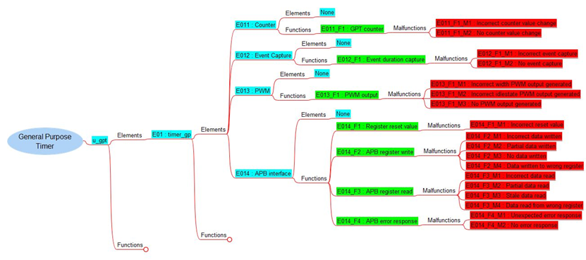
RTL study is an important pre-requisite of DFMEA. This helps in analyzing the various IP sub-modules and their functional behavior. The IP’s RTL becomes easier to understand when we go through the specification and documentation of that IP in parallel. Spec details of IP module hierarchy and the explanation of each sub-modules and their main functional features aid in better understanding of RTL. A detailed fault and structural analysis in DFMEA process is achieved by understanding each feature implementation thoroughly. Module hierarchy is shown as element branches in DFMEA. Main functionalities, CR and CSR of IP are part of DFMEA function branches.
DFMEA of IP
We start the DFMEA of an IP by creating a mind map of its elements and functions. A primary node with IP name is created first and branched into – Elements and Functions.
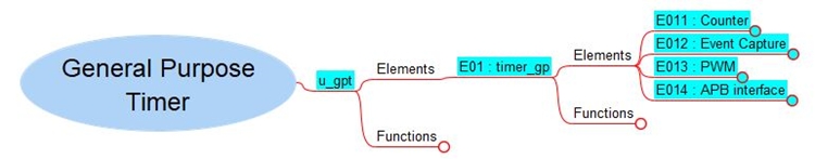
1. The sub modules of IP are listed as elements in the order
a. ‘E01’
b. ‘E02’
c. ‘E03’
and so on. These are called child elements.
Each element is further split into two branches – Element and Functions.
1.1 Sub-modules of the first child element are listed as elements in the order
a. ‘E011’
b. ‘E012’
c. ‘E013’ and so on. These are called super child elements.
1.1.1 If there are no further sub-modules then, we end the branch with ‘None’ node.
1.1.2 Various functional behavior of the first super child element is listed as ‘E011_F1’, ‘E011_F2’ and so on. Similarly functions of second super child element should be listed as ‘E012_F1’, ‘E012_F2’ and so on, and for third super child element, functions will be ‘E013_F1’, ‘E013_F2’ and so on.
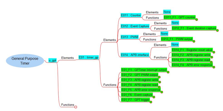
1.1.3 Each function can have several malfunctions. Malfunctions are listed assuming that all the inputs are correct. For example, if the function is ‘Generate interrupt on time out’, then the possible malfunctions could be:
a. Timer interrupt not generated on timeout.
b. Timer interrupt generated before/after timeout.
Malfunctions of super child elements are listed in the format – ‘E011_F1_M1’, ‘E011_F1_M2’, ‘E011_F2_M1,’ ‘E012_F1_M1’, ‘E012_F2_M1’, ‘E013_F1_M1,’ and so on. Malfunctions of first child element are listed in the format – ‘E01_F1_M1’, ‘E01_F1_M2’, ‘E01_F2_M1,’ and so on. Complete specifying malfunctions of each function corresponding to each super children (E011, E012, E013…) of first child (E01).
1.2 Similarly super child elements of second child will be ‘E021’, ‘E022’ and ‘E023’ respectively. Further divide these into elements and function as mentioned for first child element. Functions of first super child of second child (E02) will be in the form ‘E021_F1’, ‘E021_F2’……’E022_F1’, ‘E022_F2’, and so on. Malfunctions will be named using ‘E021_F1_M1’, ‘E021_F1_M2’…. ‘E022_F1_M1’, ‘E022_F2_M1’, ‘E023_F1_M1’….. Similarly specify malfunctions of each function corresponding to each super children (E021, E022, E023…) of second child (E02).
1.3 The same process is continued for other child elements E03, E04, and so on.
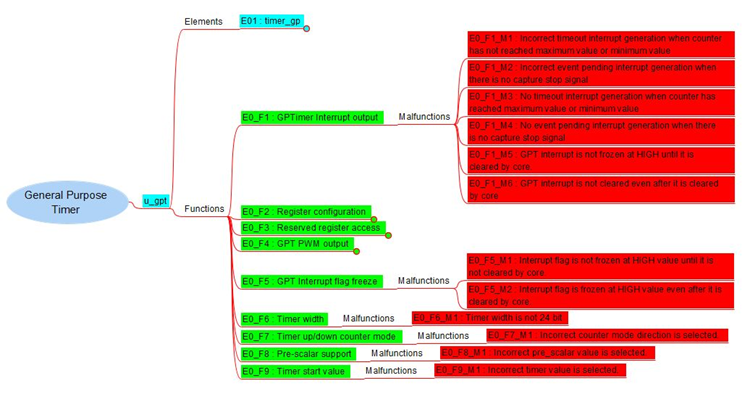
2. After completing the element details, SR, CSR and primary functions of IP are noted under Functions tab in the order – ‘E0_F1’, ‘E0_F2’, ‘E0_F3’, ‘E0_F4’… and so on. These are called top-level functions. Malfunctions of these functions are listed in the format – ‘E0_F1_M1’, ‘E0_F1_M2’, ‘E0_F2_M1’, ‘E0_F3_M1’, ‘E0_F3_M2’, ‘E0_F4_M1,’ and so on.
3. The malfunctions of the super child element (E011_F1_M1), that indirectly becomes the cause of child element malfunctions, are linked downwards to those appropriate child element malfunctions (E01_F1_M1). Parallelly, the functions of child elements (E01_F1), whose malfunctions are linked as stated before, are linked upwards to the corresponding super child element functions (E011_F1).
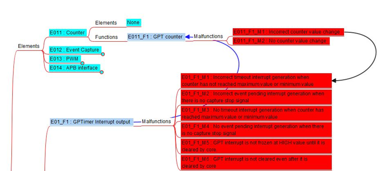
4. Similarly, the malfunctions of the child element (E01_F1_M1), that indirectly becomes the cause of top-level function malfunctions, are linked downwards to those appropriate top-level function malfunctions (E0_F1_M1). And the top-level functions (E0_F1), whose malfunctions are linked as stated before, are linked upwards to the corresponding child element functions (E01_F1).
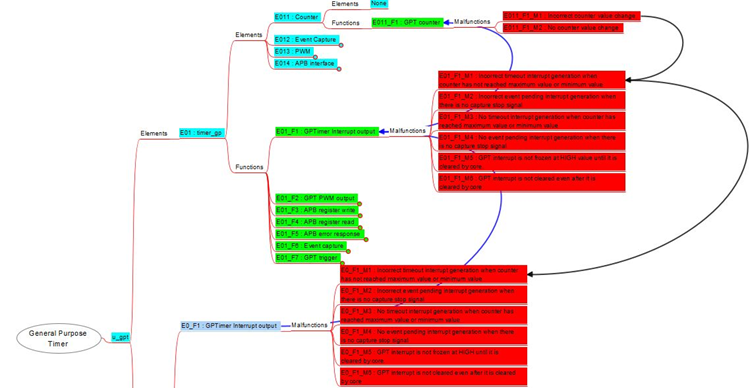
5. This process is repeated till all the IP sub modules and their functions are analyzed as mentioned above.
A ‘groovy’ script is run by highlighting the primary IP node. This script generates a list of function tree, connected functions, connected malfunctions, unconnected functions and unconnected malfunctions. This helps in simplifying the view of connected and unconnected links. Once the DFMEA is completed, this has to be reviewed and approved by the Design Inspector.
Bug fix and Sanity checks
The DFMEA file is shared and explained to verification engineers. Based on the various malfunctions created, they create multiple test cases and/or assertions re-creating these negative scenarios.
For example, General Purpose Timer either counts upwards or downwards and generates an interrupt on reaching either the maximum or minimum counter value. This interrupt stays high until it is cleared by the core.
This behavior can be tested with the help of ‘gpt_timeout_intr_clr_test’. The intention of this test is to cover and verify that after the timer reaches maximum or minimum value, timer interrupt is generated. Once the timer is generated, it should remain high until it is cleared by core. Assertions also can be used to check the interrupt behavior.
This test can be used as negative test for identifying malfunctions like ‘Timer Interrupt not triggered on counter expiry’ and ‘Timer interrupt not clearable.’
They also create additional testcases to ensure that component requirements and safety requirements are met. In case if there are any discrepancies in malfunction related tests, JIRA is created and reported to designer.
If there are no such test failures, then RTL is considered to be frozen and verification engineers concentrate on completing coverage aspect.
Next activity is to close pending IP JIRAs. For design fix, discuss the proposed changes to be made before committing. Update the fix and assign to Verification Engineer/Project manager by marking the JIRA status to ‘Resolved.’
Run Lint and CDC checks to make sure the design fixes do not yield any warnings or errors. To reduce the warnings/errors, either relevant fixes are made or they are waived after discussion.
V-plan Review
Various assertions, system level tests, block level tests and DFMEA malfunction-based tests are created and documented as Verification plan (V-plan). Multiple assertions/tests are added to ensure verification from various aspects and improve the test coverage. A more detailed explanation is provided in the verification document.
Inspection and Signoff
The Design Inspector finally verifies updated DFMEA file and reviews the malfunctions based test cases result and coverage. Once the report is clear, this IP is signed off for release.
PROS
- Disciplined manner of analysis
- Very handy in risk analysis especially with new feature additions.
- Early detection of potential threats. Its cause and effects are also mapped.
CONS
- User-dependent depth analysis.
- Usually, smaller details are ignored to reduce complexity.
- Continuous updating is required for every new threat detected.
CONCLUSION
All crucial systems of the automobile need to pass stringent functional safety requirements. Any existing or new feature addition needs to pass various tests to confirm that it complies to high grade user safety. Hence, there is a need for strategic analysis of functional features before launching automobiles to the public. There are several ways to test and verify the safety functions, one among them is DFMEA. DFMEA is a continuous, structured process useful in identifying potential failures of a system. DFMEA flow contains many sub-processes, some of them are – Function and requirement identification, listing failure and its effects, assigning priority ranks based on severity, design changes reviews to mitigate failures, actions completed and completion date.