- Radhakrishnan V
- May 25, 2022
A Hands-on Guide to Backend Performance Optimization of a SaaS platform for scalable AI workloads
This article contains a more detailed treatment of backend performance optimisation considerations in platforms targeted to handle scalable AI workloads. A brief introduction of the same can be found in our blog on Use of Celery in Serverless systems for scaling AI workloads. The platform referenced is Ignitarium’s TYQ-i® SaaS Platform (TSP), a serverless architecture that is used for delivering high performance anomaly detections for civil infrastructure and manufacturing lines. The following were some of the key platform imperatives:
- Scalability – easy to scale; as the number of algorithms and components that are deployed simultaneously increases, should not degrade the guaranteed frames per second (fps) performance
- Flexibility in terms of infrastructure – the platform should be capable of running on-premises or in standard public cloud offerings
- High performance – real-time or batch processing capabilities (mandated by the specific deployment scenario trading off latency vs throughput)
- Plug and play architecture – well defined protocols to incorporate new components from internal developers or partners
1. Simplified TSP architecture
Fig 1. shows the simplified TSP architecture; it consists of a sequence of microservices triggered by user requests from the browser. These requests are served by a set of nodes (called Workers) that are sequenced by an Orchestrator block. This article is focused on the implementation and optimization of these Workers.
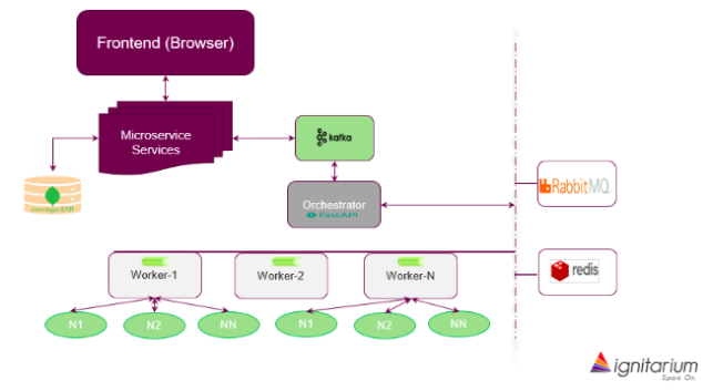
An important aspect of the platform being scalable is the choice of distributed computing. Each application has a sequence of tasks to complete which could include pre-processing (filtering, transformation, image registration, stitching etc.), AI inferencing jobs (segmentation, classification, detection) and post processing jobs. The platform should be able to support a responsive User Interface (a batch upload or viewing the result set), while tasks belonging to multiple instances of different applications are executed concurrently (asynchronously). This implies that the compute backend should have the ability to:
- fetch from an input/result queue and task queue
- push the result back to input/result queue (the output of one task may be an input to another task)
- flag the status of a task
- use standard Python functions as tasks
2. Distributed task queue
With the need for multiple tasks to execute asynchronously, we needed a distributed task queue and execution method. Our first choice of distributed task queue was Celery, though we tried alternatives as proof of concepts. Celery is a task queue implementation intended for use with web applications to offload heavy duty compute from webservers. Compared to alternatives, Celery ticked many boxes, including its compatibility with different message queues, cluster/container tools and a large user/expert community.
3. Task pipeline
Celery provides a feature named “Canvas” to develop workflows. This feature enables pre- sequencing of tasks in a pipeline. Celery does not just execute the tasks in the specified order but will also take care of passing results from one task to its successor, without needing any special coding effort. This feature can be leveraged to run a static pipeline of tasks. We used this extensively during the initial phase of platform development, being fully aware that it cannot handle decision-based execution of tasks. To illustrate the simplicity of Canvas, please refer Fig 2. In this example, tasks T1, T2a, T2b and T3 are connected. The output of T1 is fed to T2a and T2b which are parallel tasks, and their respective outputs need to be fed to T3. Using Canvas, this workflow can be built with a single statement:
chain(T1(), group(T2a(), T2b()), T3())

4. Branch executors
Canvas worked great until we faced situations where the output of a task determined the next task to run. Canvas does not link jobs as successor or predecessor dynamically. We worked around this limitation by introducing a wrapper task named ‘Branch Executor’ that will call the function or execute the task depending on the output from the previous task. Without branch executor, the execution logic is embedded in the successor branch. That is, each of the possible output branch will check if the output matches with the condition in which it should run and if not, it will return. This meant that Celery must pick up all the potential successor branches, check if the predecessor’s result matches with the condition in which the current task must execute. Such testing in all possible successor tasks will result in inefficiency and avoidable delays.
To illustrate this point, let us extend the previous example. Consider that the task T1() produces ‘a’ or ‘b’ as output and accordingly either T2a() or T2b() must be executed. We can still use Canvas in the way it was explained in our previous example (Fig 2). But the tasks T2a or T2b, (referred to as T2X) should have a logic to check if output from T1() is equal to X and if not return immediately. Apart from this, T3() will have to be ready to accept an empty response from all T2X() tasks except the one which has result from T1() matching its condition.
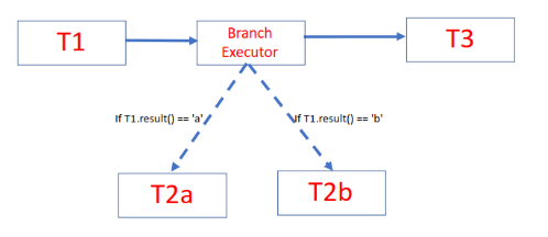
Branch executors replaced execution of all possible task options and executed only the task that should be run (Fig 3). This not only improved the performance, but also allowed us to keep the workflow simple:
chain(T1(), BranchExecutor(), T3())
However, the combination of Branch Executor and Celery Canvas too had its limitations as the number of decision boxes in the workflow increases.
5. Workflow/pipeline scheduler
Branch Executors worked just fine with Celery Canvas when the control of execution can be handed back to a main thread after execution of a single task. But, if the path chosen by the branch executor itself had to execute a series of tasks in each branch, or worse, if there were branches within branches, pre-sequencing using Canvas becomes cumbersome. This meant that it was time to move on from the ‘Canvas’ based sequencing solution.
We had to introduce a dynamic workflow author and scheduler into the platform architecture. From the set of options, we chose Airflow because of its versatility, ease of use and pluggable architecture with executors of various kinds; it employed the Celery executor, which allowed a smooth integration into our infrastructure.
Soon, we realised that though Airflow’s workflow authoring, scheduling and monitoring capabilities were excellent, task scheduling latency exceeded one second. For batch jobs, this would not have been a challenge. But, in real-time inferencing, and with sub second throughput time of each task, waiting for more than one second between tasks was certainly unaffordable. We had to find an alternative, which is simple but fast enough for our needs.
6. Custom scheduler
None of the alternatives of Airflow matched our needs, so we decided to build a custom scheduler from scratch. We arrived at a few constraints that we wanted to impose on ourselves, while developing our own replacement for Airflow. It should be
- separate from the algorithms and part of the platform/infrastructure components
- implemented without adding too many parameters
- quick and with minimal processing overhead
- easy to maintain
A light-weight scheduler was thus developed that could be plugged into the platform. When a new algorithm gets on-boarded, the task configuration (yaml file) was made available to the platform. This included the parameters for each task (algorithm specific) and infrastructure needs like GPU requirement etc. (platform specific). Two new fields – predecessor and successor for the jobs were added to the configuration file. The scheduler used this information to build the graph in a single pass over the task configuration file. The scheduler builds a list of dependents (successors) for each node. As each node completes, the status is updated, and the scheduler picks up the successor tasks of the completed task and adds them to the execution queue.
Fig 4. shows the task configuration file with non-relevant details removed and the corresponding graph created by the scheduler. Note that successor and predecessor information, though redundant, allows the construction of a dependency graph in a single scan of the yaml file.
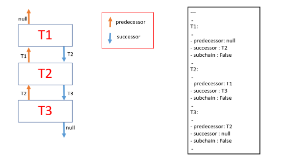
To indicate that a task is a potential starting node of a subchain, a third field was added (subchain =True/False). Complex sub chains belonging to multiple paths were stored separately and connected to the main graph on the fly. This avoided the need to traverse through all the nodes for each image as they enter the task lifecycle. Another Boolean field named ‘condition’ is used to identify nodes after which the branching will start. To demonstrate this, let us consider this example where result from T1 would determine one of the following paths from (T2a, T2a1, T2a2) or (T2b, T2b1). The yaml file and the graph constructed from the initial pass are shown in Fig 5.
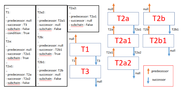
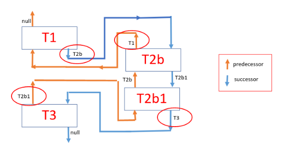
Fig 6. shows the graph modified during run time, with the result from T1 causing the Orchestrator to pick the (T2b, T2b1) path. The scheduler having access to the result from T1 will rewire the graph and the tasks get executed as per the rewired graph. Rewiring is accomplished by overriding the predecessor and successor fields of just 4 tasks (marked in red circles) – i.e., condition node (T1), subchain node (T2b), the last node in the subchain (T2b1) and the original child node of condition node (T3).
7. Performance optimization
The platform orchestrator invokes the custom scheduler as a separate thread for each image, which further reduced the impact of graph construction time on the performance requirement and isolating it from impacting other task pipelines. The custom scheduler needed about 100 lines of code and just a few additional lines in the configuration of each node (task) – the predecessor, successor, subchain (optional) and condition (optional). Further improvements to performance, abstraction and code readability were achieved by introducing the networkx library for implementation of Directed Acyclic Graphs (DAG).
We distributed the tasks in separate queues to take advantage of differing execution times. For example, smaller duration jobs were consolidated in a single queue and longer ones were split into multiple queues. Similarly, CPU intensive jobs were given a dedicated queue, while GPU queues were dedicated based on history of their graphic core needs.
We also separated workflow of projects into multiple small workflows when the execution order of a video frame mattered. This separation allowed us to get further improvement on latency to the tune of 20 to 30%.
8. Summary
Performance tuning of highly scalable AI platforms is a complex exercise and requires careful upfront architecture, numerous trade-offs and extensive PoCs. With the right mix of off-the-shelf and custom-built components, we were able to induct high performance workflow orchestration methodologies into Ignitarium’s TYQ-i SaaS Platform to meet the demanding requirements of Infrastructure analytics use cases.


