
Mixed-Signal Verification Challenges
As the complexity of Mixed-signal designs increase, so does the need to have an exhaustive, structured, and scalable approach towards the verification of such designs. Digital Verification already has such a methodology (Universal Verification Methodology), which has proven to be very successful in taping out complex digital designs with high quality and within a shorter time span. Analog verification, on the other hand is done using Spice based simulations, which is directed and time-consuming. This leads to multiple challenges in verifying mixed signal systems which need to handle both these domains in a single verification environment.
Mixed Signal Verification Methodology uses behavioral models of the Analog Blocks instead of the circuits, to speed up the simulations. There are multiple modeling languages available for this purpose such as Verilog-A/AMS, Wreal and SystemVerilog Real number Model(SV-RNM) based on the speed and accuracy requirements.
Proven Solutions and their limitations
SystemVerilog Real Number Modeling (RNM) has made it much easier to model voltages and currents as real numbers, enabling some level of Analog functionality to be modeled in System Verilog.
SystemVerilog is a powerful verification language used extensively in Digital verification. This enables one to bring in the structured and exhaustive verification approach to Mixed-signal systems too. Leading to much shorter verification times and enabling much more robust verification of the interactions between the Analog and digital domains.
With the increasing complexity of the Mixed-signal designs, it becomes imperative to be able to accurately model most of the important analog effects which could impact the system parameters and consequently, the system performance.
This leads to the question of selecting a modeling language which can provide a good trade-off between simulation accuracy and speed. Additionally, one also needs to consider the time and effort needed for setting up an integrated verification environment for mixed-signal simulations.
Digital Mixed-signal (DMS) simulations are run using event-driven digital simulators. Typically, time -discrete real-number (RNM) or Wreal behavioral models of the analog circuits are used in DMS. They leverage digital verification capabilities like Metric driven verification, System Verilog Assertions, and automated checkers to handle some of the mixed-signal verification challenges.
Wreal/RNM Models used for DMS/AMS simulations, can meet most of the current Mixed signal verification requirements, however, they model analog values as real-valued ports, which is scalar in nature and can represent either a signal voltage or signal current, which cannot be used to model loading effects¹. Also, current consumption from blocks whose supply nodes are represented as real-valued voltage ports cannot be modeled.
How can EEnet help?
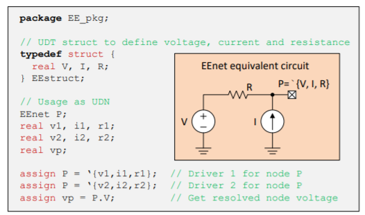
Cadence has provided the EEnet package², where EEnet is a SystemVerilog User Defined Nettype (UDN). EEnet has been able to address the above concerns to some extent. It makes modeling of Analog behavior in SystemVerilog much easier, thus improving the chances of identifying first level bugs in Digital Mixed-signal verification itself, instead of waiting for the AMS simulations which are time and effort intensive.
EEnet is a structured UDN which consists of three fields; Voltage Current and Series resistance as represented in figure 2 below,
For Low-power designs, the system current consumption is a critical specification, use of EEnet for supply nodes in SystemVerilog models during DMS/AMS verification can predict any issues in the early stages of the design cycle. A full current consumption spec verification can then later be done using a complete schematic AMS simulation.
A supply node in SystemVerilog can be modeled as a EEnode current sink, with the value of current being sunk coming from the Specification or from the individual block level schematic simulations.
A Case Study
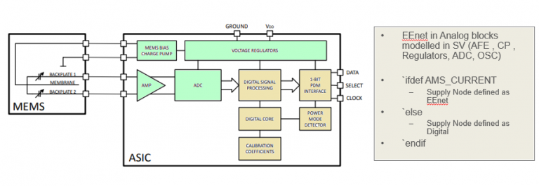
This approach was used for a customer project, where the sub-blocks of a MEMS digital Microphone were modeled in SystemVerilog with the supply nodes as EEnets. EEnet supply nodes were used as constant current sink; ‘{0.0,-block_current_value,`wrealZState};² to model the current consumption in SystemVerilog.
This was controlled through a macro for DMS / AMS simulations whenever the Block was replaced by its model.
A Microphone Block diagram³, is given below, Analog Blocks (AFE, CP , Regulators, ADC, OSC, etc.) were modeled using EENet.
Summary
Using this approach, we were able to model the current consumption in our DMS/AMS simulations. The current values modeled were static currents with one fixed value during normal operation and another fixed value during power down. The current value was controlled by the device power down/enable.
Using EEnet, the team enabled the use of SystemVerilog models for both DMS and AMS simulations, which met the project requirements. Nevertheless, there is scope for future improvements too. Current consumption was modeled as static (with just an on/off switch), dynamic current modeling can be further explored to get a more accurate measurement. Also its use for modeling supply connections for low-power AMS designs in the presence of UPF/CPF needs to be investigated further.
It has been observed that EEnet still has a few known limitations, for example¹, limited connect module support.
EEnet based SystemVerilog models can be easily integrated into the existing UVM based verification environment, which supports coverage and automated self-checking environments for Mixed signal simulations, thus bringing down the simulation times and catching fundamental bugs early in the design cycle.
References
- Enabling Digital Mixed-Signal Verification of Loading Effects in Power Regulation using SystemVerilog User-Defined Nettype Alvaro Caicedo, Texas Instruments, Freising, Germany Sebastian Fritz, Texas Instruments, Freising, Germany.
- Cadence Documentation on SystemVerilog EEnet.
- IM69D130 High performance digital XENSIVTM MEMS microphone datasheet
- Efficient methods for analog mixed signal verification Interface handling methods, trade-offs and guidelines Lakshmanan Balasubramanian, Bharath Kumar Poluri, Texas Instruments (India) Pvt. Ltd., Bangalore, India) Shoeb Siddiqui, IIT Madras, Chennai, India Vijay Kumar Sankaran, Cadence Design Systems (India) Pvt. Ltd., Bangalore, India.


5 thoughts on “System Verilog EEnet (SV-EEnet) application: Modeling block currents in Mixed Signal Verification”
Your article helped me a lot, is there any more related content? Thanks!
Thanks for sharing. I read many of your blog posts, cool, your blog is very good.
Rattling fantastic info can be found on blog.
Thank you, your article surprised me, there is such an excellent point of view. Thank you for sharing, I learned a lot.
Novyny